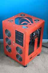
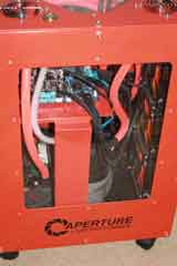
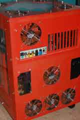
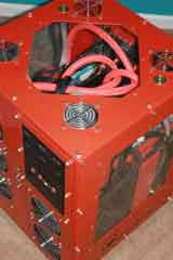
My Half-Life PC

I happened upon the computer modding website bit-tech by mistake one night and saw some of the coolest PC modding happening today. I always thought PC modding was a bit excessive; this from a guy who built a watercooled PC. I was inspired that night to start a modding project that would draw from all my experiences as a tinkerer and artist. This was also about the time I knew I had to build a new and improved gaming machine. Naturally I decided to incorporate my favorite video game into the new build. And so the Half-Life gaming rig came into being.
My gaming machines have been watercooled for about 10 years. The one aspect I do not care for is the two-component system. My first watercooled PC the extra case houses my water pump, radiator and reservoir, which is quite cumbersome. This new rig would have everything contained in one PC case. Mountain Mods PC cases were the only real choice for what I needed. It had to be aluminum and more importantly large enough to handle a second pump, radiator and reservoir.
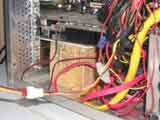
This time around I was boycotting Asus and Nvidia because of the problems I had with their EN 8800 GTX video card and Crosshair motherboard. I did not have performance issues that other gamers were having, in fact this was the best performing card I owned up to this point. I had a connection problem between the MOBO and the video card that suddenly occurred two years after the initial install. Since both products were out of warranty, I resolved the issue with a 2 X 4 and a shim (photo below). This is totally unacceptable for a video card and MOBO of this price. I had been an Nvidia and AMD fan for as long as I could remember, but AMD recently acquired ATI. Since my last card and the motherboard were Asus, I figured it was fate and time to give other manufactures my hard earned money; "Go Free Markets"!
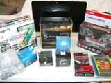
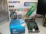
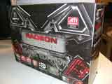
I like MSI, but GIGABYTE had a board with all the features I was looking for and the price was right. I wanted USB 3.0 and plenty of room for these massive new video cards being produced today. My first real video card was the 3Dfx Voodoo 2; yes ... life was much simpler back then. The XL-ATX form factor was ideal for two large video cards run in a CrossFire configuration. Another reason for my choice in a Mountain Mods case was the ability to have my MOBO in a horizontal position. It seemed that the problem with my last gaming rig was that the video card was too heavy and could not seat properly in the motherboard, even though the card was mounted to the case itself.
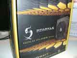
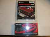
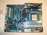

It is now time to do an initial setup of the main components. I normally don't do this step because my builds in the past were rather modest. This build however, was somewhat complex and unfortunately due to most manufacturing occurring in China these days along with PC products getting more complex everyday, odds are better today than ever that you will get a product that is defective. In fact, this is exactly what happened to me. If I didn't do this initial setup and find the problem part(s) from the start, this build would have been a suckfest.
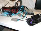
First thing to do is install standoffs on the motherboard. We want no chance of shorting anything out and we can do a quick fit to the MOBO case tray and make sure there are no surprises. Next, I installed the processor with cooling fan and in this application a chipset cooling pipe. The videocard, hardrive and optical drive goes in next. Last, is the power supply and the the monitor. This particular MOBO has a power switch built in, so I just hit the switch and watch the magic unfold. Unfortunately, I had a problem right from the start.
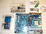
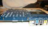
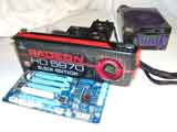
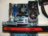
For some reason the BIOS would not recognize the optical drive. O.K. it is an OEM drive so I figured it probably was a bad drive, so I swap it for another. Still no joy. It has a brand new SATA cable but, maybe that's bad. Nope that wasn't it. How about the power cable? Even though there is power to the drive and I can open and close the drive, lets swap the cable. Still no fix. What about the connection to the motherboard? After swapping cable to various SATA connectors on the MOBO, the BIOS would not see the optical drive. How about the BIOS? Maybe it needs to be updated. No, that didn't help. Now I'm getting annoyed! I measured the voltage from the PSU, and it appeared to be fine. The last thing I tried was swapping the PSU and of course, that was the problem. Even though the voltage coming from the PSU was good, the current on the other hand was half of what it should have been. Brand new Sparkle power supply unit was DOA.
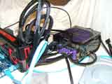
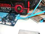
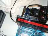
Mountain Mods Ascension-CYO was my choice for a case. One of the reasons was the ability to customize all the sides of the case. Windows on the case were important so the lights and the watercooled components could be shown off. I also wanted a top to the case that could accommodate water ports to make filling the case with water much easier. The back of the case had a second cutout for a power supply which I could use to add my water pump relay. The front panel could handle two radiators, one for my video card and a second for the processor and chipset.
A second reason for the case was the size that could house all the watercooling components. I needed something that could take two radiators, two pumps and two reservoirs. I also wanted to accommodate the new behemoth video cards that are becoming prevalent.
And finally, this case was able to have the motherboard in a horizontal position. It seemed one of the design flaws of my last gaming rig was the added pressure of a unusually heavy video card on the PCI bus connector. There would be no lateral forces on the PCI connector with this setup. In addition, there would be a solid copper waterblock attached to the video card adding to the weight. This added weight would have no ill effects on a horizontal MOBO.
Mountain Mods Asension-CYO case
- Front Panel: 140.3
- Left Panel: Big Window
- Right Panel: Big Window
- Top Panel: Diamond
- Motherboard: HPTX
- Back Panel: Horizon-10
- Acrylic Finish: Clear with Etching
- Case Finish: Brushed Aluminum
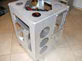
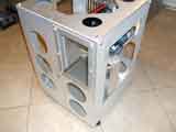
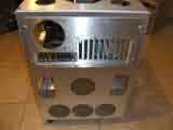
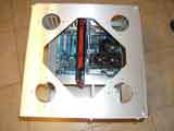
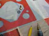
All the holes in the panels are punched out at Mountain Mods leaving sharp edges behind. Before any paint can touch this case, it will have to undergo a complete deburring of all edges. A simple deburring tool comes in handy here. I also do a preliminary mockup to check for alignment of holes of components such as the radiators, fan grills and panels to frame.
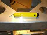
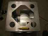
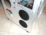
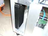
The entire case was sanded then degreased and ready for self-etching primer.
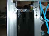
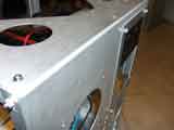
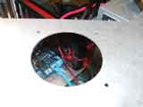
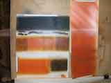
Since Half-Life is the theme, it of course needed to be painted orange. I wanted the case to have a carbon fiber feel to it. I spent a few hours testing different methods to achieve this look. I chose a base coat of orange lacquer and silver lacquer sprayed through a mask over the basecoat. The top right swatch was the technique I used.
The entire case was sanded, degreased and sprayed with a self-etching primer. Then I sprayed 3 coats of orange lacquer basecoat and let dry overnight. I taped off the inside of the drive bay before painting. This allows the swapping of optical drives without having to deal with a build up of paint making the bay a little narrower.
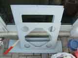
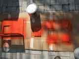
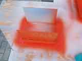
Every surface was painted except for the bottom of the case.
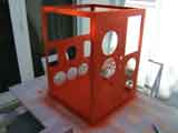
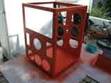
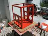
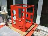
I used a roll of anti skid underlay for rugs, purchased at Walmart for the mask. The lacquer silver was sprayed very lightly in an inconsistent manner leaving behind a stripped look. I made sure to spray enough silver so I would not have to remove then replace mask and spray again. I sprayed silver on the panels and the front and back of frame only. None of the interior was sprayed with silver because I wanted to simplify the project.
After the silver came the clear coat. I sprayed 6 coats of clear because of all the wet sanding I was going to do.
I made a mistake by leaving a side panel with fresh clearcoat on wax paper in the hot sun and forgot about it for several hours. The result was wax paper stuck to the clearcoat that had to be removed. I wet sanded with 400 grit sandpaper to remove paper then the usual 800 - 2000 grit sandpaper to get the gloss finish I was looking for.
The "Black Mesa" and "Aperture Laboratories" labels as well as the mask for the plexiglass floor were provided by a local sign shop.
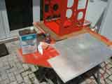
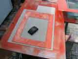
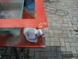
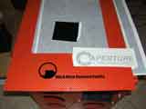
At this stage I knew where most components would go but was still unsure exactly how to work out the details. I needed to start installing PC components and check all the clearances.
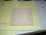
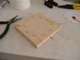
I cut the plexiglass floor down and filed the edges smooth. I had to notch the floor so it would clear the MOBO support. I also made notches for the wiring to come through for the lighting underneath. I placed a small section of plywood under the plexiglass to provide support for the floor itself. The wood also gives a way to secure the water pumps to the floor. The plywood thickness provides the necessary clearance for the floor LEDs.
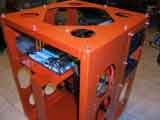
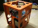
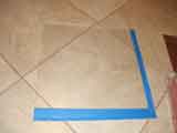
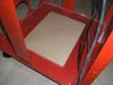
I did not put the floor decal from the sign shop on yet, because I wanted to be able to see underneath the floor so I could place the water pumps over the plywood for proper mounting.
Although the last two photos were taken after the reservoirs were built, it illustrates how the simple act of cutting the plywood is not so simple. As you can see from the last picture, the case is filling up and I'm quickly running out of real estate. The plywood needs to be big enough for the water pumps, but not so big that the LEDs won't fit.
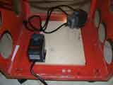
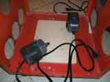
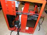
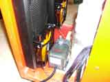
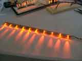
The LEDs came next. There are three levels of LEDs in the case and LEDs surrounding each reservoir. The case is what I focused on first since I have to finish the floor in order to start installing everything on top of it. There are 4 LED strips on each level and each strip contains 10 LEDs. There is a level under the top of the case, another under the MOBO tray and the final level is under the plexiglass floor. The floor is completely covered with vinyl except for a 1/4" strip which encircles the floor.
The first job was to breadboard the lights and to get a sense of luminosity and current draw. I bought my LEDs from HKJE LED Lamp Center on Ebay at a great price. I ordered amber and UV colors. Each color required a different voltage to get the same intensity, which means each strip had to have the same color lights. I split the colors in half around the case, which means each layer has 20 amber and 20 ultraviolet lights.
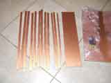
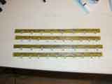
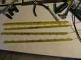
I was designing and building the printed circuit boards myself. I bought my PCB material from abcfab on Ebay. I ordered FR-4 single and double-sided. I cut the single sided FR-4 into 12 strips for the case. The circuit for the strips was designed on Corel Draw. I used Staples "Photo Basic Gloss Paper", hot iron and muriatic acid to make all my PCBs.
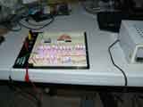
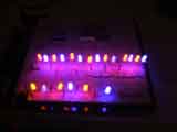
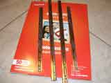
After attaching the LEDs, I tined the exposed traces, attached wire and then tested each strip.
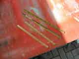
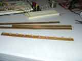
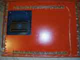
The strips were glued into place with a hot glue gun. The photos below show the floor vinyl and connectors for the LEDs.
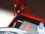
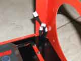
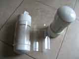
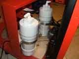
Time to build the reservoirs. I wanted to be able to run LEDs around the circumference of each reservoir in 4 different layers. I bought all the PVC parts and fittings at Lowes and the clear acrylic tube at McMaster-Carr. I got the tap at Ace hardware. I used a piece of poplar to mount the reservoirs to the MOBO brace.
I have four fittings per reservoir. An inlet from the radiator, an outlet to the water pump, another inlet on top which is connected to a fitting at the top of the case for filling the system and another outlet for draining the system.
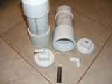
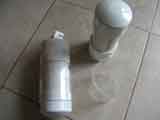
I used the same method people use to control LED cubes to control the reservoir LEDs. This keeps the number of wires to a minimum. There are 10 LEDs in each level and 4 levels which gives a total of 14 wires to control every LED.
I built a jig to hold the LEDs in place as I solder a single ring for every level. I left one side open so I wrap the ring around the reservoir and solder it closed. This was done four times. The LEDs were a bit too large for the acrylic tube to go over, so I filed the edges down so they could fit. I use a lot of hot glue; We do not want any shorts after everything is assembled.
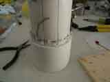
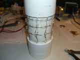
I tested the LEDs at every step to make sure there were no shorts or bad LEDs. I notched the PVC cap to allow the wires to pass. All the wires terminate at a 14 pin molex connector which will have a corresponding connector at the controller.
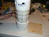
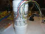
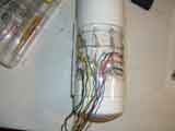
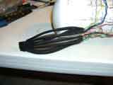
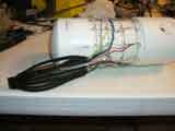
The wires are hidden nicely with braided sleeving and heat shrink tubing. I bought all my sleeving and heat shrink material at FURRYLETTERS on Ebay.
I painted the inside black and sandblasted the inside of the acrylic tubes to cut down glare and hot spots. The reservoirs are ready to go.
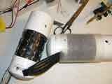
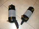
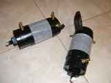
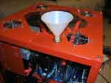
Danger Den is still my favorite place for watercooled PC stuff. I did not want to open the case to fill the system with water. These brass fill ports are a nice clean touch. I used a stepbit and a deburring tool to get a clean cut hole for the fill ports.
The last picture shows the "Half-Life" etching in the top window. I had the Half-Life logo etched on both side windows as well. I would not have minded if the etchings were a little more prominent, but I still like the subtlety they provide.
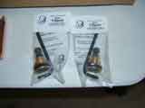
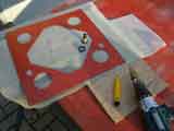
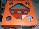
I love the way these hard drives are mounted, simple and elegant. Thank you Mountain Mods.
I used a square Bell box to house the relay components for the water pumps. The water pumps turn on when there is voltage to the case fans.
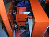
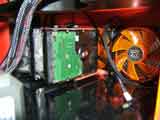
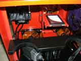
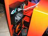
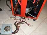
I used an old power supply to test the relay for the water pumps. I made a fan junction box which supports the multiple fans and the water pump relay system. The box takes a standard 4-pin PC molex and provides 10 3-pin fan connections.
I lengthened the fan wires where needed then sleeved and heat shrinked for a clean look.
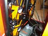
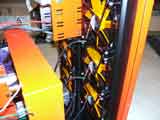
Time to get the rest of the watercooled parts together and installed. Danger Den supplied the video card and CPU waterblocks. A chipset waterblock came with the GIGABYTE motherboard.
Below are pictures of the back of the video card before and after I removed the heatsink.
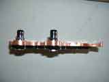
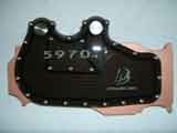
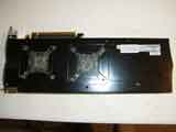
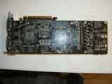
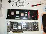
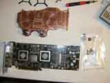
Below are pictures of the front of the video card after I removed the OEM heatsink. Instructions come with the waterblock for easy replacement. I use Arctic Silver 5 for all my heatsink applications.
I chose to use "Neon Red" sleeving for most of the water lines. This product looks more orange than red and it is UV reactive. It has a cool glow when the UV LEDs shine down on it.
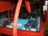
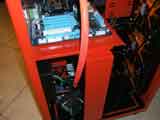
The water loops start with reservoir, go to the water pump, then go to video card or CPU, go to the radiator and finally back to the reservoir.
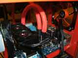
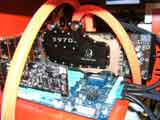
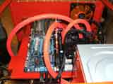
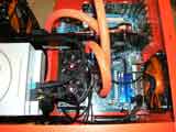
I covered the ends of the sleeving with heat shrink tubing and a zip tie.
I recommend getting the "Clean-Cut" sleeving over the regular stuff. This may not be possible, such as my case where I wanted a particular color which was not available in "Clean-Cut". The normal sleeving cuts easy, but if you handle the ends too much the sleeving begins to fray. This is apparent in the last picture here where the tubing runs into the top of the reservoir.
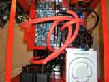
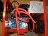
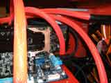
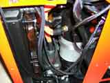
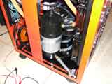
Time to fill the system with water. The second picture shows the drain on the reservoir. I used a straight stop valve for the drain.
I sleeved the remaining wires inside the case.
Not only did I want LED lights inside the case, but an LCD panel displaying various Half-Life characters was a must.
Since the beginning of this project, I have been working on learning how to use and control both the Arduino and Sanguino development boards. The Arduino Duemilanove uses an ATmega328P microcontroller. The 328P was going to control all functions of the LEDs. The Sanguino uses the ATmega644P core. I chose the 644P for the LCD control because of the larger onboard memory. This allowed for more pictures to be displayed without having to add any external memory.
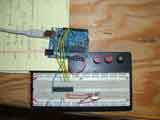
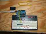
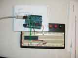
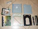
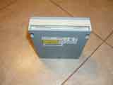
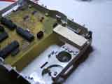
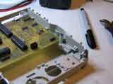
This is a DVD drive that was bad, so I took it apart and left nothing but the shell. I kept the old control board as a template for the new PCB I was building. There was room left over for another PCB that would supply power and I mounted another PCB on top of the DVD enclosure.
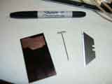
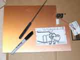
The last photo shows the critical tools needed for making PCBs. The Sharpie is used for repairing traces before the copper is etched. The utility knife blade and pin is used to remove copper material after etching. Occasionally, very small traces are not etched completely and a short between traces remains that needs to be removed.
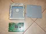
I made an interface board for my Nokia LCD screen. This simply provides an easy connection between the LCD and the microcontroller. After I created my schematics in CadSoft Eagle, I copied them onto heavy card stock so I could easily fine tune the dimensions of the PCB. It is a lot easier to notch a piece of cardboard than a PCB.
I took the card stock and transferred the perimeter shape onto the new PCB material.
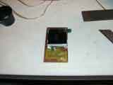
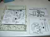
After ironing the photo basic paper onto the new PCB it is soaked in a bath of water to remove the paper. You are left with the toner on the copper.
Next step is to bathe the PCB in muriatic acid to remove the copper. The last image shows how I left the PCB in the acid too long and the small copper traces on the right side of the board were broken. I soldered small wires in its place because I was too lazy to make another board. I apologize for the blurry images here.
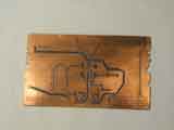
I tested continuity on every circuit on the board before I populated with components. The second picture shows the trace repairs.
The last photo shows the board installed and ready for next step.
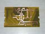
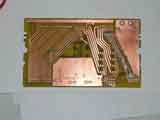
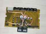
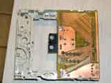
Another picture showing the board installed. The hardest part of a 2-sided PCB is getting the two sides to register properly. Precision is critical here.
The last two photos show the LCD control board which is mounted on the outside of the DVD case.Again, I apologize for the blurry images.
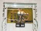
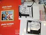
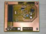
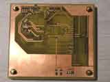
I made another mistake which was easily corrected with a couple of regular resisters. It is hard to get everything just right on the first run. I welded a piece of steel on the front of the DVD case, which will fill 2 spots on a DVD drive bay nicely. Notice the small holes drilled on the top. This is where the LCD control board will go. I ran the power and communication wires through the large hole.
The last photo shows the opening for the LCD screen. Notice the interface board for the LCD has a bunch of wires soldered on it. The LCD connector was extremely difficult to work with. The copper traces were hard to etch and soldering the connector to the board was even harder.
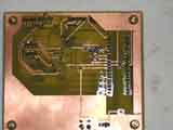
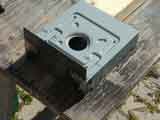
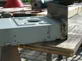
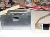
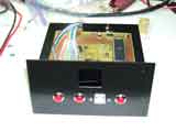
I drilled the remaining holes for the controller front panel. The USB port is for uploading code to the 644P processor. There are three buttons with various functions. One controls how the LCD images are displayed. Another controls the different functions for the LED stripes in the case. The last button controls the LEDs on the reservoirs.
I tested all connections before I installed the boards. I mounted two reset buttons on the top of the controller unit for both processors in case I had problems. I made all the cables from scratch.
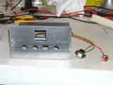
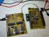
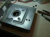
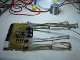
I tried using a piece of wood to hold the PCB in place, but in looked hack and did not work as well as I hoped. My second attempt was better; just a simple screw.
The last two photos show the finished controller inside and outside the PC case.
This is the finished PC.
